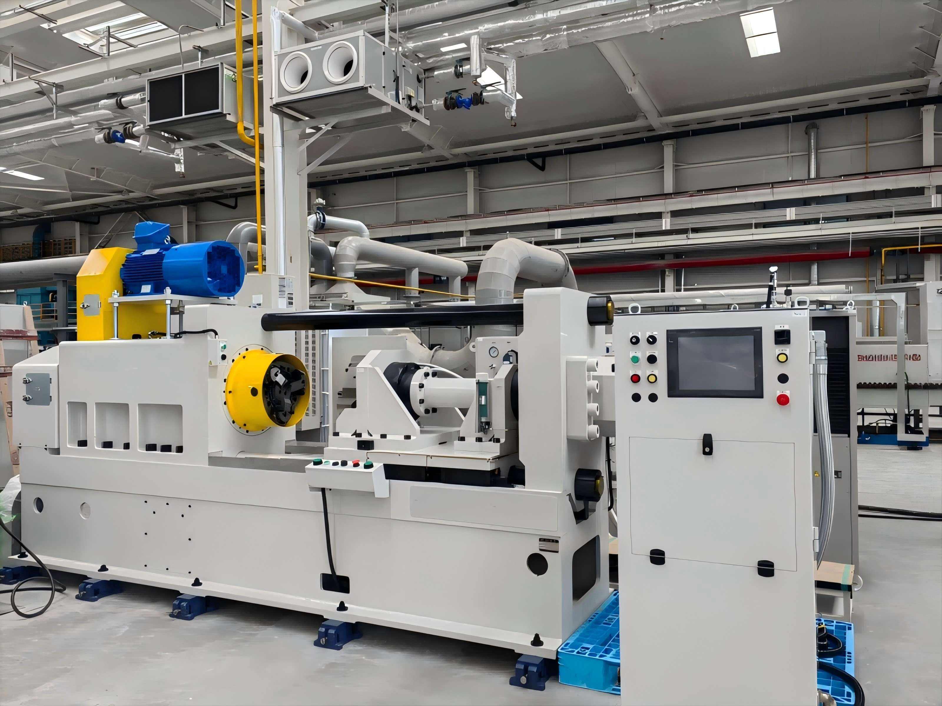
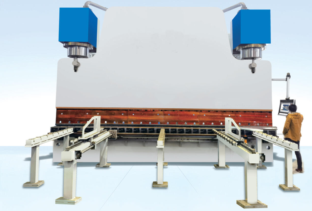
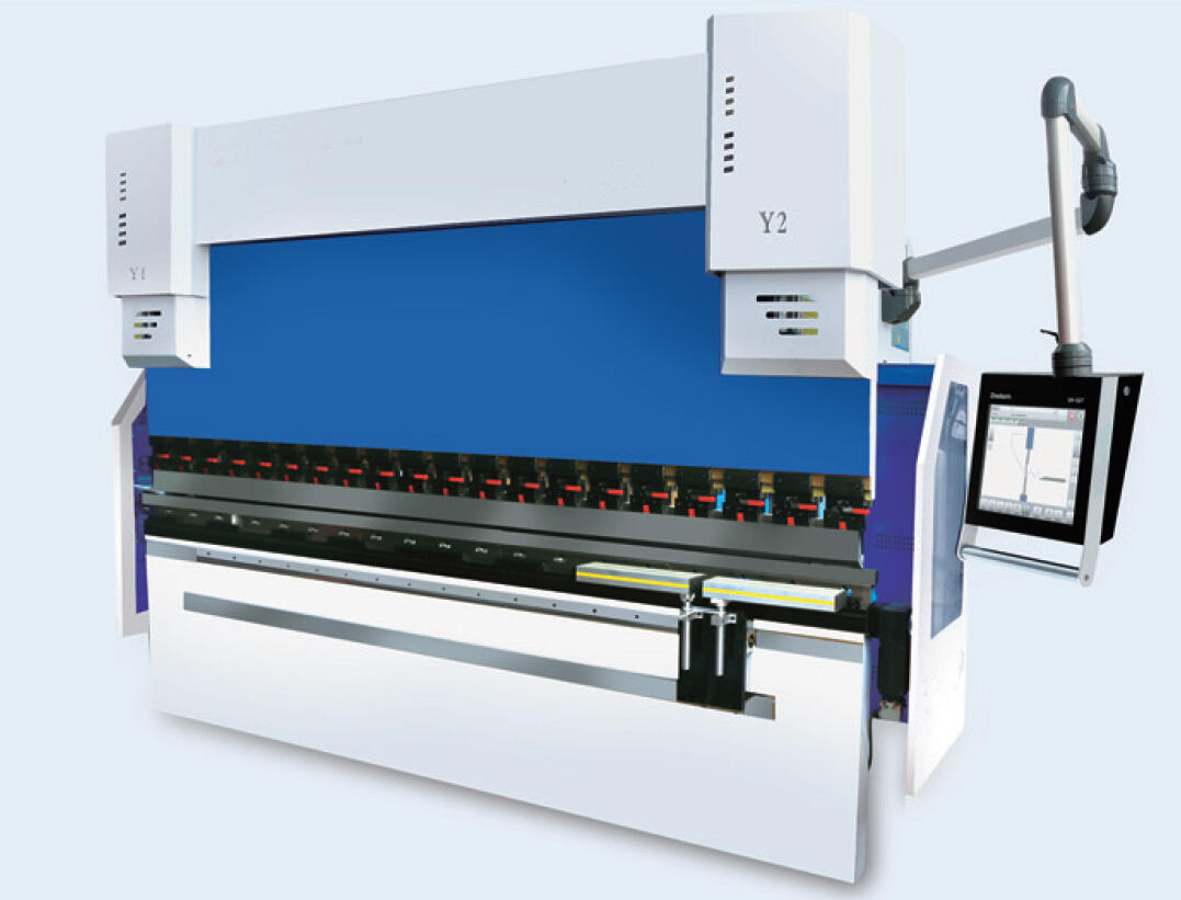
A hydraulic bending machine is a high performance industrial device that uses hydraulic power to shape metal sheets, plates, and profiles into precise angles, curves, or complex forms, renowned for its ability to deliver high force, consistent pressure distribution, and exceptional control—making it indispensable in heavy duty metalworking applications. Unlike mechanical bending machines, which rely on flywheels and mechanical linkages, hydraulic models utilize one or more hydraulic cylinders connected to a hydraulic pump, reservoir, and control valves to generate force, allowing for smooth, adjustable pressure application across the workpiece. This design enables hydraulic bending machines to handle thick materials (from 1mm to over 100mm in thickness) and high strength alloys such as stainless steel, titanium, and high tensile steel, which are common in aerospace, shipbuilding, and construction industries. The core components of a hydraulic bending machine include the frame (usually a C frame or H frame for stability), the upper beam (housing the punch), the lower beam (housing the die), hydraulic cylinders (typically two for balanced force application), and a control system (manual, semi automatic, or CNC). CNC integrated hydraulic bending machines offer advanced programmability, allowing operators to store bend sequences, adjust force and speed parameters, and synchronize with backgauges for precise workpiece positioning—critical for achieving tolerances as tight as ±0.05mm in applications like mold making and precision engineering. One of the key advantages of hydraulic systems is their ability to maintain constant force throughout the bending stroke, ensuring uniform deformation even in long workpieces (up to 6 meters or more), where mechanical machines might suffer from force degradation. This uniform pressure minimizes springback—the elastic recovery of the material after bending—by allowing operators to overbend slightly to compensate, resulting in more accurate final dimensions. Hydraulic bending machines also feature overload protection, where pressure relief valves prevent damage to the machine or tooling if the force exceeds safe limits, enhancing durability and reducing maintenance costs. Tooling for hydraulic bending machines includes a wide range of punches and dies, with V dies being standard for angular bends (90°, 135°, etc.) and specialized dies for forming channels, boxes, or custom profiles. The selection of die width is critical: a general rule is that the die width should be 6 8 times the material thickness to prevent cracking, though this varies by material type and tensile strength. In operation, the workpiece is placed on the die, the backgauge positions it accurately, and the hydraulic cylinders lower the punch into the die, applying force until the desired bend is achieved. Modern hydraulic bending machines often include features like crowning systems (mechanical or hydraulic) to counteract beam deflection in long workpieces, ensuring parallel bends across the entire length. Energy efficiency has also improved with variable displacement pumps, which adjust flow rate based on demand, reducing power consumption compared to fixed displacement systems. Compliance with international standards such as ISO 6927 (hydraulic fluid power systems) and EN 12625 (safety requirements for bending machines) ensures that these machines meet global safety and performance benchmarks, making them suitable for use in diverse industrial environments from automotive plants in Europe to shipyards in Asia.