
Core Dial Indicator Calibration Procedure
Step-by-step calibration using certified gauge blocks and ring gauges
Secure the dial indicator properly in a calibrated testing stand first. Check the zero point using a certified Grade AA gauge block to set up our baseline readings, aiming for accuracy within plus or minus 0.0001 inch. Next step is moving through different measurement points usually around 10%, 50%, and 90% of the full scale range. We use ring gauges that can be traced back to NIST standards for this part. Take note of any deviations at each spot along the way. What counts as acceptable varies depending on the type of indicator we're dealing with. For high precision metrology grade tools, we look for no more than 0.0005" variation, while workshop models generally allow up to 0.002". According to OIML R 59 guidelines, it's good practice to run three separate tests at every calibration point just to make sure results are consistent. If we see backlash over 0.0003" or hysteresis beyond 0.0004", that means something needs fixing right away before continuing with further work.
Critical reference point alignment and zero-setting protocols
Getting the reference plane aligned right makes all the difference, according to those precision engineering papers we've been reading lately. Around 80 something percent of measurement accuracy depends on this alignment alone. When setting up, make sure that contact point sits at a right angle to whatever surface is being tested. Keep any tilting below 3 degrees because otherwise cosine error starts messing things up. To get the indicator set to zero, turn that bezel around until the needle lines up with the main mark on the scale. Apply just enough pressure during measurement, somewhere between half a Newton and one Newton force. Parallax remains a big problem out there in the field, causing roughly a fifth of all errors. Look straight at the dial face when checking readings instead of from an angle. Test it properly by doing three separate measurements on a known good flat surface. If results differ by more than 0.00015 inches, then something's wrong either with how tight everything is, worn parts, or maybe just plain old bad alignment somewhere along the line.
| Calibration Parameter | Tolerance Threshold | Failure Impact |
|---|---|---|
| Backlash | < 0.0003" | Intermittent measurement jumps |
| Hysteresis | < 0.0004" | Directional measurement variance |
| Repeatability Error | < 0.00015" | Non-reproducible readings |
| Cosine Error Alignment | < 3° | Systematic under-measurement bias |
When to Calibrate: Frequency Guidelines for Dial Indicators
Usage-based models: High-cycle vs. intermittent applications
How often equipment needs calibration really depends on how much it gets used day to day, not just what the manual says. Take those busy production lines where quality control teams run over 500 tests every single day. The constant wear and tear means monthly checks become necessary to keep things accurate. On the flip side, when instruments sit idle most of the time in research labs or prototype testing areas, going three months between calibrations usually works fine. Equipment tends to drift out of spec faster when pushed hard all the time, which explains why some facilities end up scheduling more frequent maintenance sessions during peak seasons or heavy workload periods.
- Critical tolerance demands: Instruments verifying features under 0.001" require verification more frequently than standard schedules
- Documented drift: Historical calibration records showing >0.0003" deviation signal the need for accelerated intervals
- Application severity: Manufacturing settings reduce optimal calibration windows by 50"“70% compared to baseline guidance
Impact of mechanical shock on cumulative error (0.0002""“0.0005" over 6 months)
Just one 3 foot fall onto concrete creates an instant error of around 0.00035 inches, which is basically what happens after about six months of normal wear and tear. These kinds of shocks really mess things up for gear trains, making them less accurate by roughly 37 percent. Spindles get out of alignment too, and bearings start wearing down faster than expected. All this means those regular calibration schedules we rely on just don't work anymore. For equipment used in places where drops are common, like during field service visits or right there on the factory floor, getting everything recalibrated within 48 hours after any kind of impact becomes absolutely necessary if we want to keep measurements reliable and trustworthy.
Environmental Influences on Dial Indicator Accuracy
Temperature effects: Quantifying thermal expansion (1.2 µm/°C per 100 mm stem)
When it comes to dimensional stability, thermal expansion plays a major role. A steel indicator stem that's 100 mm long will expand roughly 1.2 micrometers for each degree Celsius increase in temperature, which amounts to a noticeable drift of over 0.0005 inches. Most precision workshops keep their temperatures stable within plus or minus 1 degree Celsius. But in aerospace calibration labs where accuracy matters most, they go even stricter, maintaining temperatures within just 0.3 degrees up or down for critical tools. Technicians out in the field who aren't working in climate-controlled spaces need to remember to adjust their measurements using temperature correction formulas whenever the surrounding temperature differs by more than 2 degrees Celsius from what was present during initial calibration checks.
Humidity and condensation risks in metrology workspaces
When relative humidity goes over 60%, it really starts to cause problems for spindle mechanisms through increased corrosion risks. Gear assemblies absorb moisture at these levels too, which speeds up the development of backlash issues. Quick changes in humidity (more than 10% per hour) can mess with gauge block dimensions and lead to condensation forming on contact points. This affects friction characteristics and sometimes causes those annoying false zero shifts that throw off measurements. Labs that have ISO/IEC 17025 accreditation typically keep their environments around 40 to 50% relative humidity using positive pressure ventilation systems to stop outside air from getting in. For anyone working in areas where humidity is high, desiccant storage cabinets become pretty much necessary if they want to maintain accurate readings when indicators aren't being actively used.
Root Causes of Dial Indicator Inaccuracy
Gear train wear and backlash (>0.0001") degrading resolution by 37%
When gears get worn down from constant operation, they start developing backlash greater than 0.0001 inches. This creates hysteresis problems where the pointer lags behind actual spindle movements when direction changes occur. In industrial settings where equipment runs continuously, this kind of wear can cut resolution effectiveness nearly in half sometimes reaching around 37% loss. The worn tooth surfaces allow more space between them than what was originally designed for, which is why regular maintenance becomes so important. Lubricating parts at set intervals helps quite a bit, but eventually gears need replacing after about half a million operating cycles to maintain proper accuracy levels. Keeping track of these maintenance schedules isn't just good practice it's actually required for meeting those ISO 9001 standards many manufacturers have to follow for quality control purposes.
Spindle damage, contamination, and operator-induced parallax errors
When spindles bend or bearings get distorted after being dropped accidentally, it creates binding problems that go beyond 0.0005 inches tolerance. Particulate contamination like metal shavings left over from machining, coolant residue sticking around, or even dust particles can really mess up smooth vertical movement and hide where actual contact happens between surfaces. Parallax errors are still one of those everyday mistakes people make when reading instruments. Looking at an analog dial from an angle instead of straight on causes misreadings as big as 0.002 inches which is actually 20 percent of what's considered normal for a 0.010 inch measurement range. To combat these issues caused by both human error and environmental factors, shops need to put strict handling rules in place and train their operators every six months or so. These practices help catch problems early before they become bigger headaches down the line.
FAQ Section
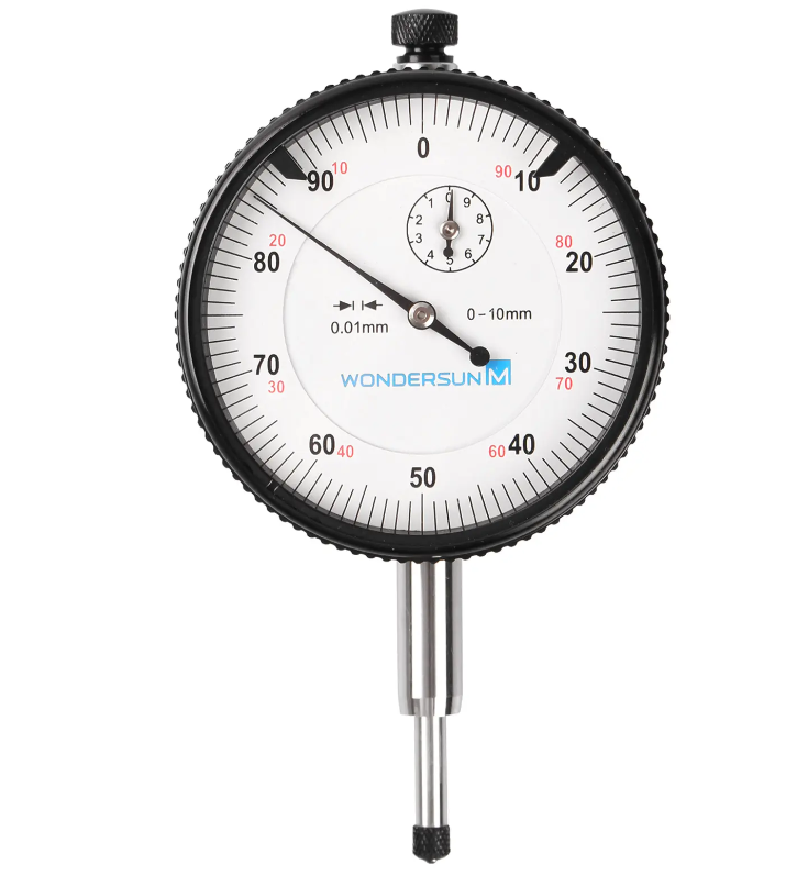
What is a dial indicator?
A dial indicator is a precision measurement device used to measure small distances or angles. Typically used in machine shops for calibration and alignment tasks.
How often should dial indicators be calibrated?
The calibration frequency of dial indicators depends on usage. High-cycle applications may require monthly checks, while intermittent usage may only need calibration every three months.
What environmental factors affect dial indicator accuracy?
Temperature, humidity, mechanical shock, and cleanliness can significantly impact the accuracy of dial indicators.
How to handle parallax errors when reading dial indicators?
To avoid parallax errors, always view the dial indicator straight on rather than from an angle.